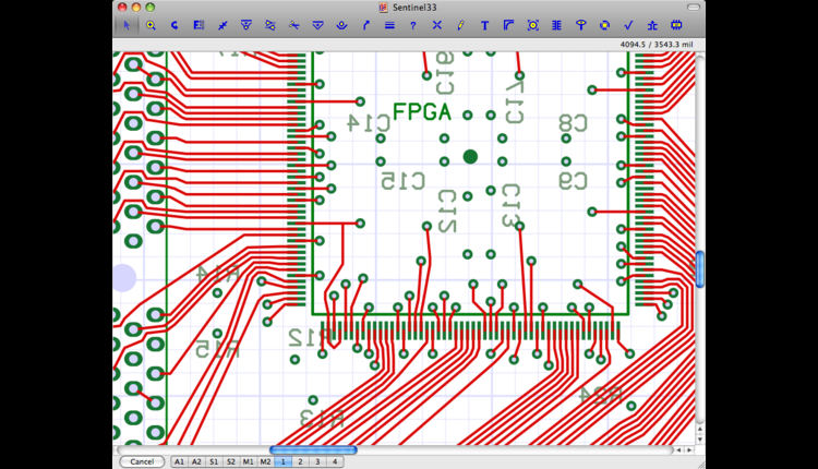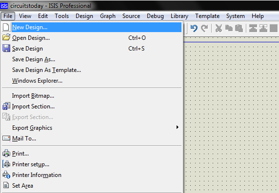
Getting Started with OrCAD PCB Designer.From the Capture schematic to the PCB layout.Convert the OrCAD Layout Footprint libraries into the PCB Editor Footprint libraries.

If the if the new wiring is not satisfactory, you can always use the Undo command. Left-click to choose the final position of the block. Suppose you want to move and drag a selection window as if it were a single line segment: left-click “Move” icon ( in the toolbox ) , Move segment or segments group (To move a wire segment or a group of segments) Note: in order to work, the cable connected to the object can not have a label, otherwise ISIS will think you want to drag the object. If you place the mouse pointer everywhere between the ends of the wire, there will be a corner and you can drag the corner of the line. There are some special methods that can be used to wiring two components. If the auto-repeat function is on, It allows you to connect different wires or pins to the bus, simply connecting the first and following each pin with a double click, the connection will be carried out automatically. The repeat wiring function copies a complete line path. Double-click the E, and it will be wired with F. Double-click the C, and the repeat wiring function is activated, the wiring between C and D is done automatically. Suppose you want to connect an 8-byte ROM data bus to the main data bus circuit, we have the ROM, and the bus as the one placed in the picture below.įirst, left-click A, and then left-click B, draw a horizontal line between the A and B. This is very useful when you want to set directly between two connection points for example in the case of a diagonal path. The other way to skip the WAR mode is by using the Tools menu in the WAR command to disable it. left-clicking another connection point to complete.
#AUTO CREATE A PCB FROM SCHEMATIC PROTEUS 8 MANUAL#
If you just left click on the two connection points, WAR will select a suitable path, but if you point a connection point, then one or several non-connected point position, ISIS will think that you are in the manual alignment path, the line will allow you to click on each corner of the path.


This feature is enabled by default, but that feature can be disabled in two ways. The wire automatic path function eliminates the need for you to draw each specific path wire. On the other hand, if you want to decide the alignment path, simply click the left mouse button at the desired point you wish a corner. if you want that ISIS automatically gives away the line path, simply left click on another connection point. Left-click the first object connection point. Connection between two objects: Line automatic path function ( Wire Auto – Router or WAR)


 0 kommentar(er)
